Home
DVL - Doppler Velocity Logger - is a Hydro-acoustic unit which uses acoustic beams to measure distance to bottom surface and the velocity which the unit is moving across the surface. It estimates velocity relative to the sea bottom by sending acoustic waves from the four angled transducers and then measure the frequency shift (doppler effect) from the received echo. By combining the measurements of all four transducers and the time between each acoustic pulse, it is able to accurately estimate the speed and direction of the movement of vehicle.
| MECHANICAL | |
|---|---|
| Device diameter | : 66 mm |
| Device height | : 25 mm |
| Device weight (air) | : 250 g |
| Device weight (submerged) | : 185 g |
| Depth rating | : 300 m |
| Materials | : Stainless steel 316 (housing) + PEEK (transducer caps) |
| Operating temperature | : -5 to 60 °C |
| ELECTRICAL / INTERFACE | |
| Input voltage | : 10 - 30 V |
| Power consumption | : 0.25 A at 12V |
| Power-on current surge | : 1.25 A at 12V |
| Physical interface | : 8 wires (pwr/serial/Ethernet) and cable (uncut 3 meters; PUR 6.7 mm diameter) with interface module |
| Indicator | : Status LED (Power, Lock) |
| Communication | : UART 115200 baud serial 3,3V + Ethernet |
| Protocols | : Water Linked WebUI demo + Water Linked API |
| ACOUSTIC / PERFORMANCE | |
| Transducer frequency | : 1 MHz |
| Transducer setup | : 4-beam convex Janus array |
| Transducer beam angle | : 22.5 degrees |
| Ping rate | : 4-26 Hz (adaptive to altitude) |
| Sensor assist | : Integrated AHRS/IMU (Yost Labs TSS-NANO) |
| Min altitude | : 5 cm |
| Max altitude | : 50 meters (Performance at altitudes > 35 meter is dependent on seabed conditions, salinity levels etc.) |
| Max velocity | : 3.75 m/s |
| Velocity resolution | : 0.1 mm/s |
| Long term accuracy | : ±1.01 % (Standard version) or ±0.1 % (Performance version) |
For detailed specs, technical details, engineering drawings, please refer to Hardware Integration
Integration of the DVL-A50 into ArduPilot Companion currently exists as a branch to the ArduPilot Companion Git repository:
https://github.com/bluerobotics/companion/tree/dvl
Follow these steps to use the DVL code:
- Go to the DVL GUI "Configuration" page. In "Network configuration" set "Static IP" with IP address 192.168.2.95 (subnet prefix 24, gateway: 192.168.2.1 dns 192.168.2.1). Click "Apply" and then power cycle the DVL.
- As of 01-06-2021, the installed companion version on the BlueROV2 is
0.0.24-14-gd62f472. Current newest version is0.0.26but not installed due to this unresolved bug). See https://bluerobotics.com/learn/bluerov2-software-setup/#update-software to check for updates. - Make sure the CompanionPi is connected to the internet (Check this by visiting http://192.168.2.2:2770/network)
- Navigate to http://192.168.2.2:2770/git
- Click "origin" -> "branches" -> "dvl"
- Click "update"
- Wait until the update is over and the Companion reboots
- Refresh the page and "Water Linked" should show up in the navbar
-
No green light: Power is off.
-
Flashing green light (slow): DVL loocking for bottom lock.
-
Fixed green light: DVL has bottom lock. The LED is mostly on and blinks quickly to show we are alive.
Main Reference of this chapter: DVL-Protocol by WaterLinked
dvl web-GUI: http://192.168.2.95/#/
dvl setting: http://192.168.2.2:2770/waterlinked
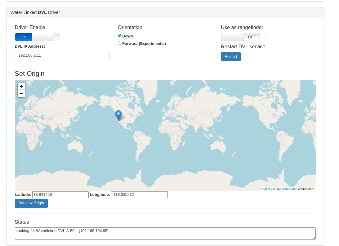
| Control Variables | description |
|---|---|
| Driver Enable | Enables or disables the DVL Driver |
| DVL IP Address | Inital IP where the driver will try to find the DVL. The driver always attempts to find Waterlinked-dvl.local (mDNS hostname) in the local network, if that fails, it falls back to the IP address in this field. |
| Orientation | Orientation of the DVL: Down is the suggested use, where the DVL points to the ocean floor, Forward is an untested mode where the dvl is mounted forward to lock position to a vertical surface in front of it. |
| Use as Rangefinder | Allows the DVL to be used as a rangefinder (shown in QGC). |
| Restart DVL Service | Restarts the DVL service. |
| Set New Origin | Used for dead reckoning; this makes the ROV show up in QGC at the selected location. The position displayed in QGC is calculated by the autopilot independently of the position showed in the Water Linked DVL web interface, which is calculated by the DVL itself. |
| Status | Shows the current Driver status, useful for troubleshooting. |
The serial communication format is 115200 8-N-1 (no hardware flow control).
Packets sent to and received from the DVL start with a w and end with LF or CR+LF. The packet format is:
| Start byte | Direction | Command | Options (0 to many) | Checksum | End byte |
|---|---|---|---|---|---|
w |
c or r
|
x |
,[option] |
*xx |
\n or \r\n
|
Direction is command (c) for commands issued to the DVL and the DVL replies with direction set to response (r).
The commands can be sent as a string or entered one char at a time from a terminal.
The protocol can support Water Linked DVLs with different feature sets.
The DVL always returns a checksum. The checksum algorithm is CRC-8 and it is formatted as a hexadecimal number using 2 lower-case charaters (ex: *c3).
Commands in the table are shown without the checksum for readability.
| Command | Description | Response | Description |
|---|---|---|---|
wcv |
Get protocol version |
wrv,[major],[minor],[patch]
|
Protocol version. eg: wrv,2.1.0
|
wcw |
Get product detail |
wrw,[name],[version],[chipID],[IP address]
|
Where type is dvl, name is product name, version is software version, chip ID is the chip ID and optionally the IP address if connected to DHCP server: eg: wrw,dvl-a50,1.4.0,0xfedcba98765432 or wrw,dvl-a50,1.4.0,0xfedcba98765432,10.11.12.140
|
wrx,[details below]
|
Velocities measured. See details below | ||
wr? |
Malformed request: Response when packet cannot be understood | ||
wr! |
Malformed request: Packet does not match the given checksum |
The DVL supports sending velocity updates using the Transmission Control Protocol (TCP). The DVL runs a TCP server on port 16171. Each packet sent contains a velocity report from the DVL on JSON format.
Velocity report is outputted after each measurement has been completed. The expected update rate varies depending on the altitude and will be in the range is from 2-26 Hz. The X, Y, Z axis are oriented according to the marking on the DVL. The messages are delimited by newline.
The velocities measured response is on the following format:
wrx,[time],[vx],[vy],[vz],[fom],[altitude],[valid],[status]
wrx,[time],[vx],[vy],[vz],[fom],[altitude],[valid],[status]
| Variables | Unit | description |
|---|---|---|
time |
ms | Milliseconds since last velocity report |
vx |
m/s | Measured velocity in x direction (m/s) |
vy |
m/s | Measured velocity in y direction |
vz |
m/s | Measured velocity in z direction |
fom |
m/s | Figure of merit, a measure of the accuracy of the measured velocities (m/s) |
altitude |
m | measurement of the distance between the transducer and the bottom (m) |
valid |
boolean | bottomlock and valid altitude and velocities (y/n) |
status |
0 for normal operation, 1 for high temperature warning |
Velocity report is outputted after each measurement has been completed. The expected update rate varies depending on the altitude and will be in the range is from 2-26 Hz. The X, Y, Z axis are oriented according to the marking on the DVL.
Example where velocities are valid:
wrx,112.83,0.007,0.017,0.006,0.000,0.93,y,0*d2
wrx,140.43,0.008,0.021,0.012,0.000,0.92,y,0*b7
wrx,118.47,0.009,0.020,0.013,0.000,0.92,y,0*54
Example where velocity and altitude is not valid and high temperature warning is given:
wrx,1075.51,0.000,0.000,0.000,2.707,-1.00,n,1*04
wrx,1249.29,0.000,0.000,0.000,2.707,-1.00,n,1*6a
wrx,1164.94,0.000,0.000,0.000,2.707,-1.00,n,1*39
Transducer report is outputted after each measurement has been completed. The expected update rate varies depending on the altitude and will be in the range is from 2-26 Hz.
The distances measured form each transducer is on the following format:
wrt,[dist_1],[dist_2],[dist_3],[dist_4]
| Variable | Description |
|---|---|
| dist_1 | Measured distance to bottom from trancduser 1 (m) |
| dist_2 | Measured distance to bottom from trancduser 2 (m) |
| dist_3 | Measured distance to bottom from trancduser 3 (m) |
| dist_4 | Measured distance to bottom from trancduser 4 (m) |
Example where velocities are valid:
wrt,15.00,15.20,14.90,14.20*b1
wrt,14.90,15.10,14.80,14.10*ac
Example where distance is not valid on transducer 4:
wrt,14.90,15.10,14.80,-1.00*53
wrt,15.00,15.20,14.90,-1.00*71
{"time":126.04666137695312,"vx":0.009757072664797306,"vy":0.002016076585277915,"vz":-0.0002864645794034004,"fom":0.00016600292292423546,"altitude":1.8710078001022339,
"transducers":[{"id":0,"velocity":-0.002349231392145157,"distance":2.041400194168091,"rssi":30.97574806213379,"nsd":19.906816482543945,"beam_valid":true},
{"id":1,"velocity":-0.0034521492198109627,"distance":1.9942001104354858,"rssi":38.42657470703125,"nsd":30.263219833374023,"beam_valid":true},
{"id":2,"velocity":0.00183798186480999,"distance":2.0886001586914062,"rssi":31.835567474365234,"nsd":22.06237030029297,"beam_valid":true},
{"id":3,"velocity":0.0029014351312071085,"distance":2.041400194168091,"rssi":37.41792678833008,"nsd":23.786922454833984,"beam_valid":true}],"velocity_valid":true,"status":0,"format":"json_v1"}
{"time":429.1646423339844,"vx":0,"vy":0,"vz":0,"fom":2.661566972732544,"altitude":-1,
"transducers":[{"id":0,"velocity":0,"distance":-1,"rssi":-37.079925537109375,"nsd":25.96938133239746,"beam_valid":false},
{"id":1,"velocity":0,"distance":-1,"rssi":-46.16178894042969,"nsd":19.031171798706055,"beam_valid":false},
{"id":2,"velocity":0,"distance":-1,"rssi":-38.94984436035156,"nsd":25.094785690307617,"beam_valid":false},
{"id":3,"velocity":0,"distance":-1,"rssi":-37.11658477783203,"nsd":26.229419708251953,"beam_valid":false}],"velocity_valid":false,"status":0,"format":"json_v1"}
{
  "time": 170.52674865722656,
  "vx": -0.00563613697886467,
  "vy": -0.007631152402609587,
  "vz": -0.007641898933798075,
  "fom": 0.001959984190762043,
  "altitude": 0.6173566579818726,
  "transducers": [
    {
      "id": 0,
      "velocity": -0.007625679485499859,
      "distance": 0.6769760251045227,
      "rssi": 38.66838836669922,
      "nsd": 18.295578002929688,
      "beam_valid": true
    },
    {
      "id": 1,
      "velocity": -0.0034413286484777927,
      "distance": 0.6769760251045227,
      "rssi": 35.403541564941406,
      "nsd": 19.518909454345703,
      "beam_valid": true
    },
    {
      "id": 2,
      "velocity": -0.006717036943882704,
      "distance": 0.6653040051460266,
      "rssi": 41.03888702392578,
      "nsd": 20.25017738342285,
      "beam_valid": true
    },
    {
      "id": 3,
      "velocity": -0.01045388076454401,
      "distance": 0.6536320447921753,
      "rssi": 31.09071922302246,
      "nsd": 17.366933822631836,
      "beam_valid": true
    }
  ],
  "velocity_valid": true,
  "status": 0,
  "format": "json_v1"
}
WaterLinked provides a package that turns the json output to ROS message.
Find the DVLs IP address (192.168.2.95). Once that's done, the package and it's components can be run by following these steps:
To run the publisher that listens to the TCP port and sends the data to ROS
rosrun waterlinked_a50_ros_driver publisher.py _ip:=192.168.2.95where _IP is replaced by the IP of the DVL, in our case 192.168.2.95. You can also display the raw DVL data in the terminal by specifying the argument "do_log_data":
To run the publisher that listens to the TCP port, displays the raw data in the DVL and sends the data to ROS
rosrun waterlinked_a50_ros_driver publisher.py _ip:=192.168.2.95 _do_log_data:=trueTo run a subscriber node that listens to the DVL topic. Helpful for debugging or checking if everything is running as it should be. Choose between "subscriber_gui.py" and "subscriber.py". The non-GUI version is used here due to limitations of companion pi with commandline interface.
rosrun waterlinked_a50_ros_driver subscriber.pyAlternatively, publish DVL message as ROS message:
  $ roscore
  # for server node:
  $ rosrun comm_tcp server_node 16171
  # for client node:
  $ rosrun comm_tcp client_node 192.168.2.95 16171
The published ROS message looks like this:
std_msgs/Header header
  uint32 seq
  time stamp
  string frame_id
float64 time
geometry_msgs/Vector3 velocity
  float64 x
  float64 y
  float64 z
float64 fom
float64 altitude
waterlinked_a50_ros_driver/DVLBeam[] beams
  int64 id    #Transducer ID
  float64 velocity    #Velocity reported by transducer
  float64 distance    #Distance value
  float64 rssi    #RSSI
  float64 nsd    #NSD
  bool valid    #Report if beam is locked on and providing reliable data
  bool velocity_valid
int64 status
string form